The last few months have been quite the rollercoaster for us, from Putin's unjust invasion of Ukraine, to me starting a new job... And only recently have I had the headspace to get back to the AR2
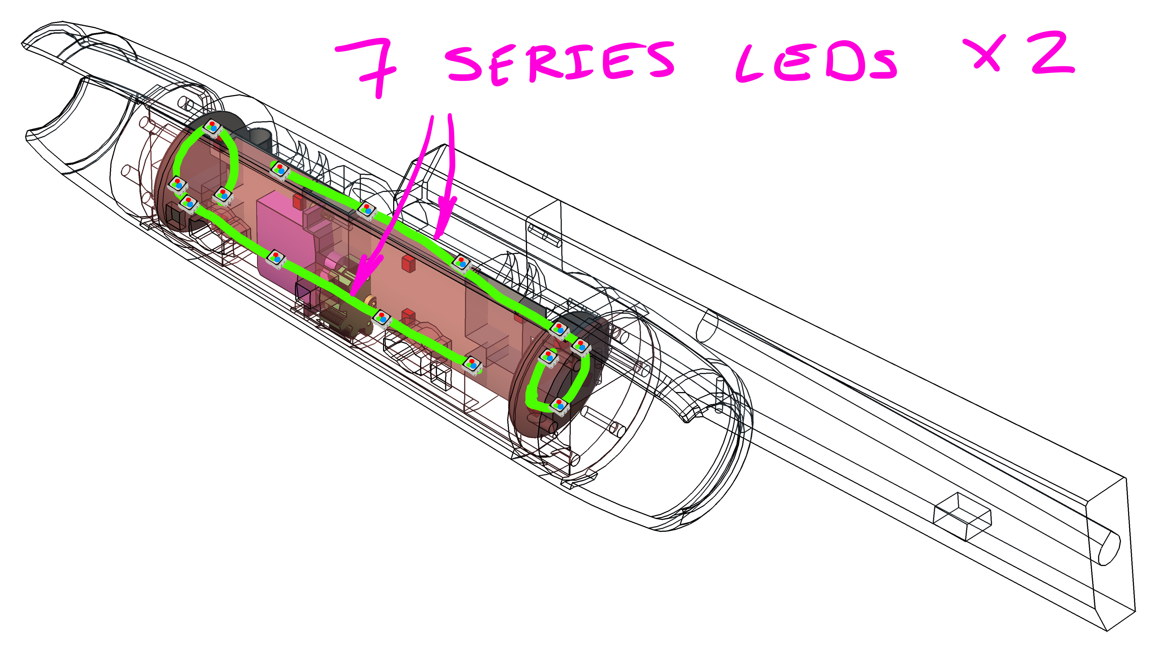
So in this quick update I want to show yous the revised RGB LED driver configuration. Basically I will be halfling the barrel LED zones from 4 (2x3S & 2x4S) to 2 (2x7S). Doing so reduces the complexity of the barrel PCBA's (like halfling the RGB LED driver IC's from 4 to 2, and lowering the LED connector pin-count from 28P to 16P), which is a welcome change as each RGB LED driver (LT3496) goes for ~13AUD/pc in low quantities
Now you might be asking, why not just drive all the 14 RGB LEDs in a big series configuration? Well I tried to simulate this scenario and soon realised that the forward voltage drop for the big LED chain would be too much for the LT3496 (who's SW pin is rated to 45V). I should also mention that I configure the OVP (Over-Voltage Protection) to 35V, so anytime the SW pin goes beyond this the IC shuts down for that switching cycle. Lastly below is the total forward voltage drop of each LED chain, and as you see in both cases we are over the 45V/35V limit:
- RED ⇒ 2.6Vf * 14 ⇒ 36.4Vf-tot
- GRN/BLU ⇒ 3.5Vf * 14 ⇒ 49.0Vf-tot
While if we break up the chain into half (2x7S) we are nicely under the limit:
- RED ⇒ 2.6Vf * 7 ⇒ 18.2Vf-tot
- GRN/BLU ⇒ 3.5Vf * 7 ⇒ 24.5Vf-tot
So with all that out of the way, here are the latest simulations of the 2x7S RGB LED configuration:


And here is an updated power losses & expected temperature rise (per IC) table:
| IC | Type | RθJA, [°C/W] | IC losses average, [mW] | IC losses maximum, [mW] | Temp above ambient, [°C] |
| LT3496 | Switching | 34°C/W | RED 68mW GRN 57mW BLU 57mW |
RED 113mW GRN 91mW BLU 91mW |
6°C to 10°C |
Couple of interesting things to note with above simulations/table:
- I highly suspect that the LTspice model I am using for the BLU/GRN LED is not the best as I am seeing massive ON/OFF & OFF/ON transients (like in orders of 100's of mA). I am certain that the peak current would be more closer to that of the RED LED simulation (~20mA above nominal), but to test this I plan to place an inline 0R jumper which I will then use to measure the actual peaks with a fancy oscilloscope at work
- The RED LED channel is showing a higher power loss, this is due to the RED LED current being double that of the GRN/BLU channel (40mA vs 20mA). So think greater I²R losses
No comments:
Post a Comment